Pokemon BDSP Automatic Egg Hatcher Overview
This project automates the egg hatching process in the Pokemon BDSP game by
automating button presses on the Nintendo Switch Joycon. The implementation
utilizes SPDT switches and the Raspberry Pi Pico's GPIO. The SPDT switch
bridge points on the joycon to emulate a button switch; while the GPIO controls
which buttons to turn on and off.
Video
Below is a demonstration of the automated button press circuit.
Context
This project emulates presses that go up and down the map while continuously
pressing the ZL button to handle the egg hatching animation.
The intended workflow for this project is to have your party full of eggs,
then run the program to have your eggs automatically hatch while
you do something else.
Implementation
-
Joycon Pairing
It is important to first pair the Joycon to the Nintendo Switch as the power for the Joycon will be from USB. Solder jumper wires to the 5V and GND pins on the Joycon connector to make it breadboard friendly. When USB power is connected to the circuit, pressing the upper pushbutton will pair the Joycon to the Nintendo Switch. You will need to do this everytime you power the circuit on. Leaving a separate left Joycon connected to the Nintendo Switch will allow you to freely move your in-game player when the automated circuit is turned off.
Note: You will be unable to use the connected left joycon if the automated circuit is turned on.
-
Joycon Test Points
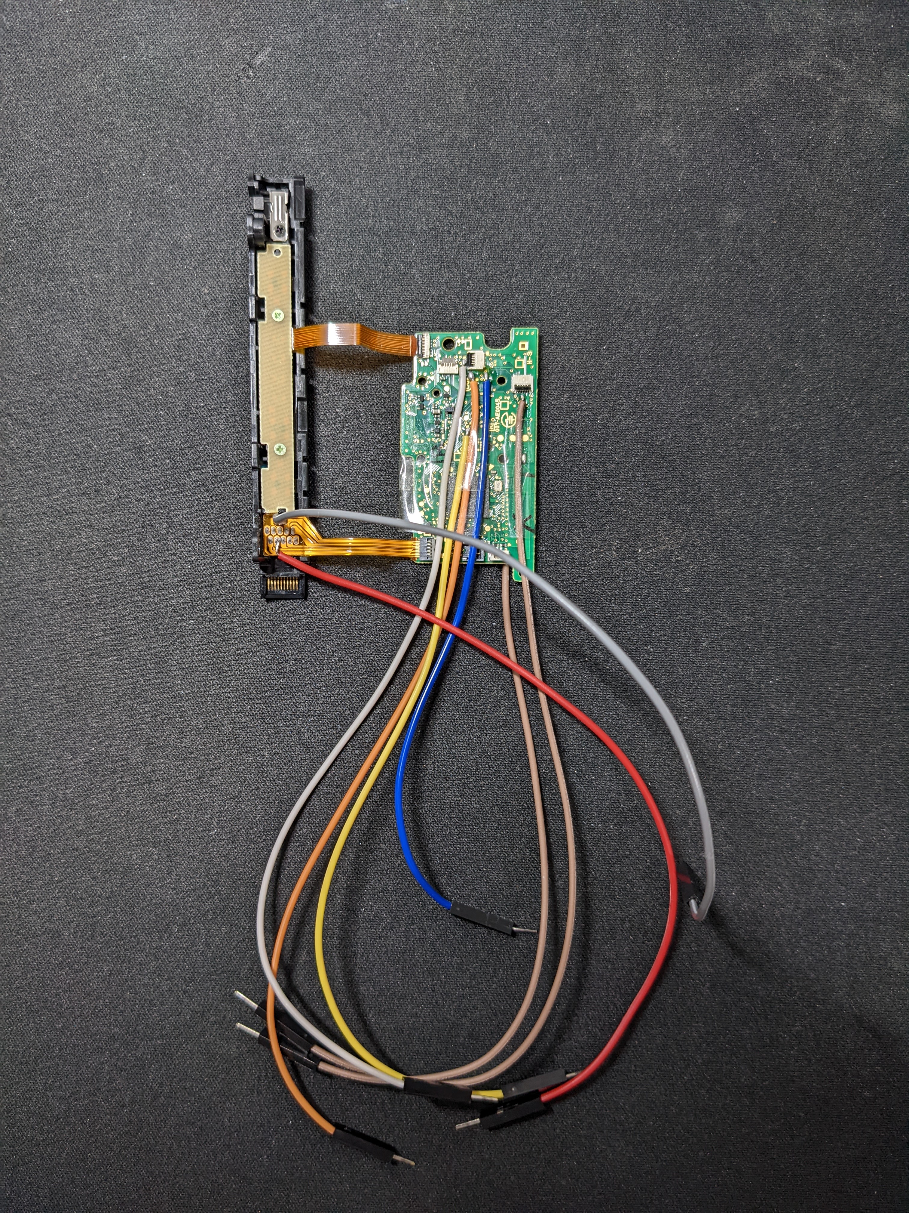
Left Joycon PCB (Front)
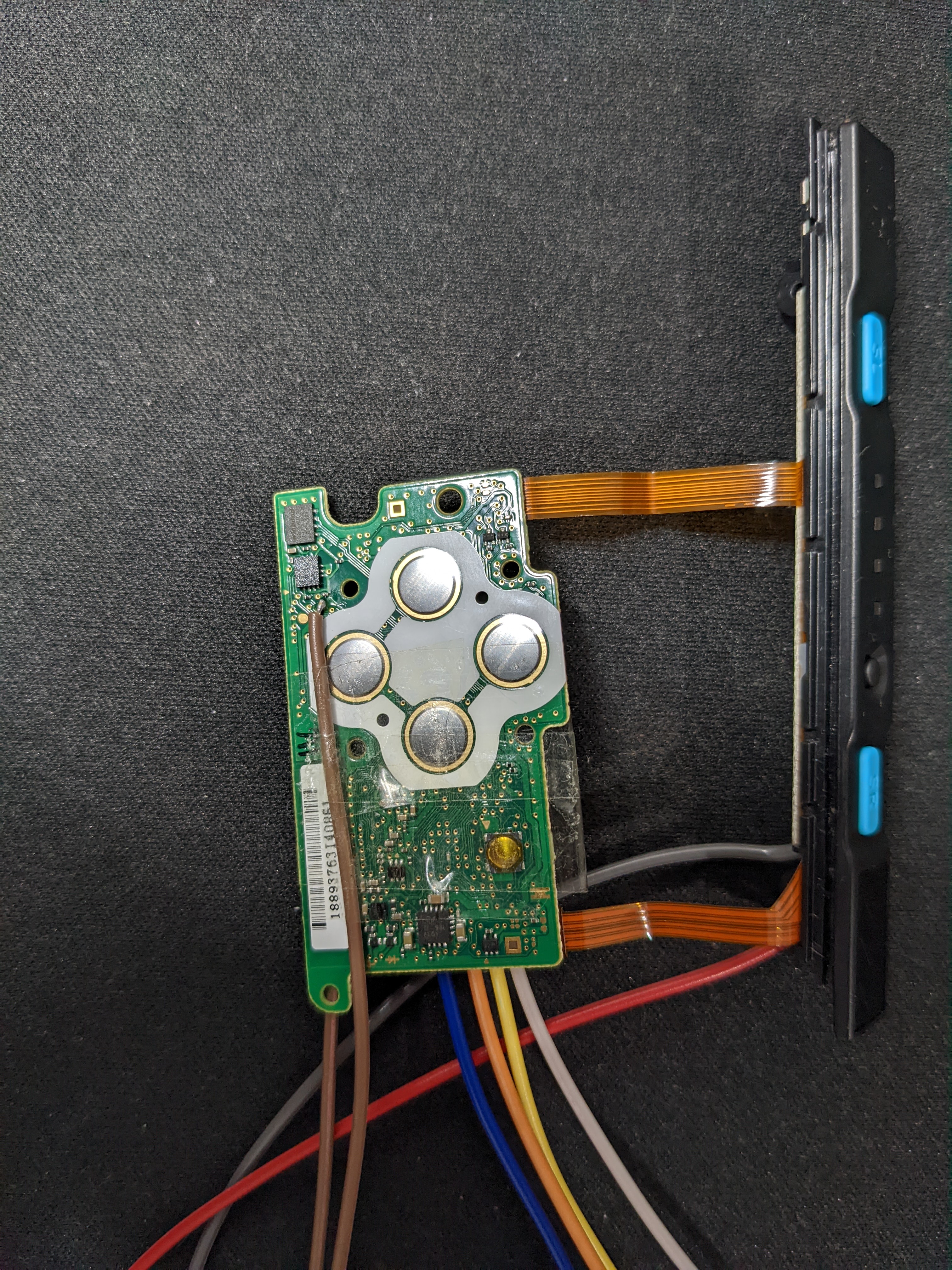
Left Joycon PCB (Back)
Using the left Joycon pinout from dekuNukem's repository, I found that emulating a button press requires the COL to be bridged with other test points. In this application, I bridged COL with UP/DOWN/ZL to emulate the up, down, and ZL button press. I soldered jumper wires to these test points making it easy to use with the breadboard.
Later on the project, I found that the Joycon's joystick was providing unwanted movement to my in-game player. The joystick corresponds to the POTX and POTY test points. To register the position of the joystick as center, I applied roughly 0.8V to the POTX and POTY test points.
In the above images, the color of the jumper wires correspond to the following test points. Red is 5V, gray is GND, blue is UP, yellow is DOWN, white is ZL, orange is COL, and the two brown correspond to POTX and POTY. -
Circuit
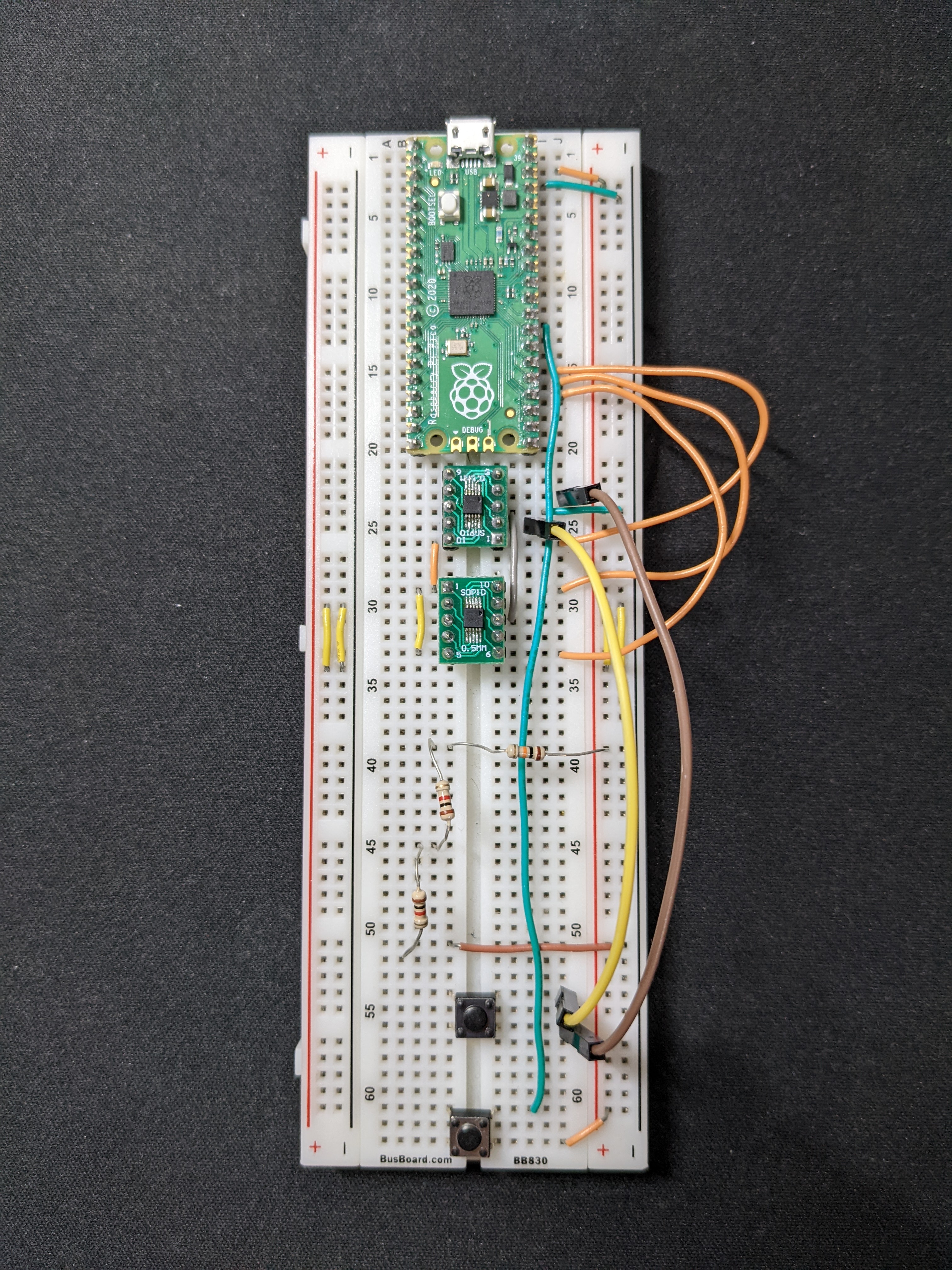
Circuit
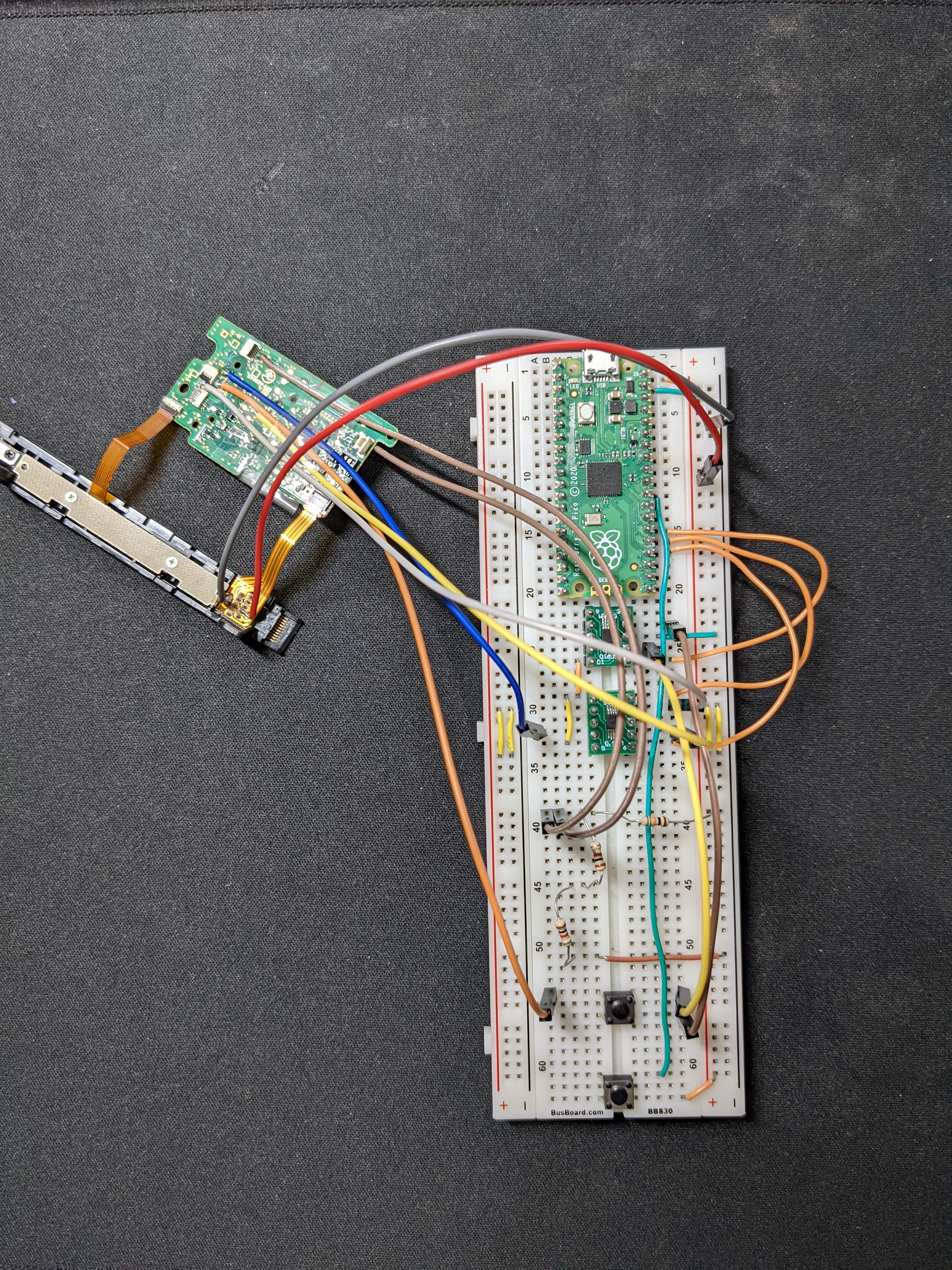
Left Joycon connected to Circuit
The circuit uses the GPIO of the Raspberry Pi Pico to control the output of SPDT switches. The SPDT switches bridge the COL with the UP/DOWN/ZL test points to emulate a button press. The GPIO controls which buttons to press by switching between the 2 outputs of the SPDT switch. I used two SPDT switches in this project: one to control COL; and the other for pressing UP/DOWN/ZL.
I used a voltage divider to provide the POTX and POTY with 0.8V. Additionally, a pushbutton is added to allow the program to run and stop.
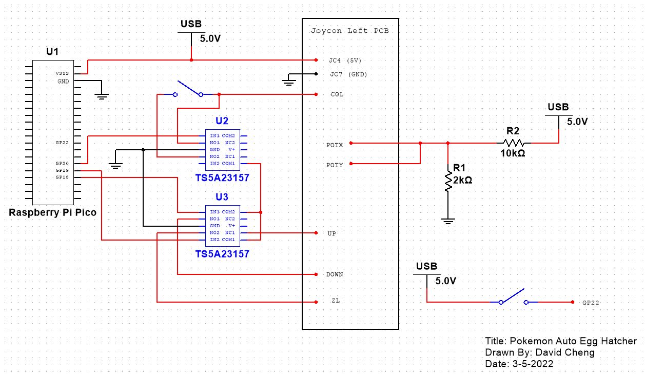
Circuit Schematic
Setup
Code can be found at my GitHub repository page here